Helicopter flight training has never been more rewarding! Our flight training system is guaranteed to get you interested in flying and proficient in controlling the helicopter. Our flight instructors are anxious to help you out any time!
Please start by reviewing our current service bulletins on the SB page.
The following manufacturer's instruction and assembly manuals will help you in assembly, operation and maintenance of your Heli-Chair: At the bottom of the page are some images you will find helpful in operation of the Heli-Chair.
Heli-Chair Assembly Instructions (0.3Mb)
Heli-Chair Pilot's Operating Handbook (0.3Mb)
Kyosho Caliber 30 Construction Manual (7.2Mb)
Heli-Max Micro Piezo Gyro Installation Manual (0.1Mb)
Kyosho Caliber setup on the Futaba 7C radio (0.1Mb)
You will find the following web-links very particularly useful for obtaining help with your Heli-Chair:
www.towerhobbies.com A great place to purchase supplies such as fuel and replacement parts
www.kyosho.com Kyosho makes tons and tons of remote controlled models, they have been around for a long time.
www.futaba-rc.com Futaba radio control website, FAQ's and other information
www.runryder.com Popular helicopter forum, lots of advice if you search for it
Heli-Chair re-assembly instructions:
Draft 1, 14 Jan 2005
Tools
Blue Loctite (available at local auto store)
Screwdriver
Allen Wrenches (included in the Helicopter kit)
Crescent wrench or wrench assortment
Dikes or "side cutters" or "wire cutters" (pliers that cut)
=================================
Helicopter:
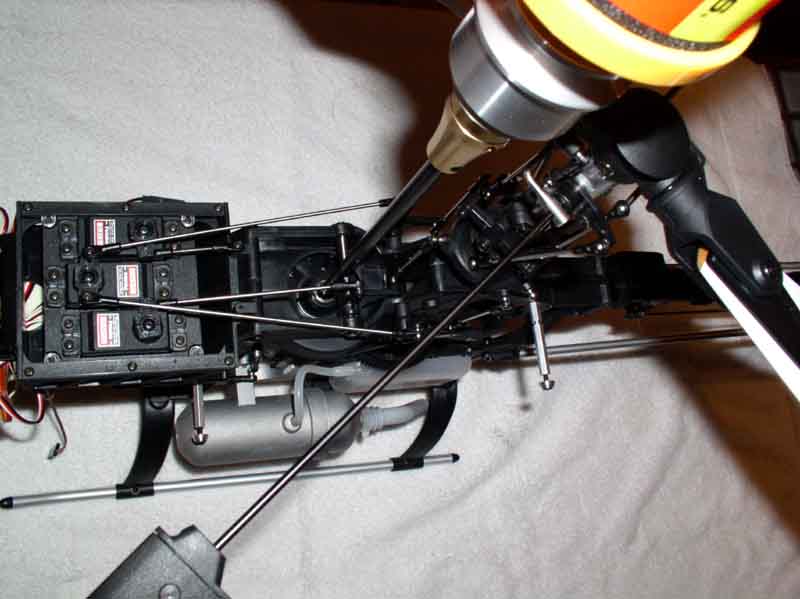
Refer to Caliber instruction manuals and photographs for further guidance.
Remove the canopy by unscrewing the two aft mounting bolts with an allen wrench. The forward mounting bolts were not installed and are in the accessory bag. Pull the sides of the canopy apart and slide the canopy forward.
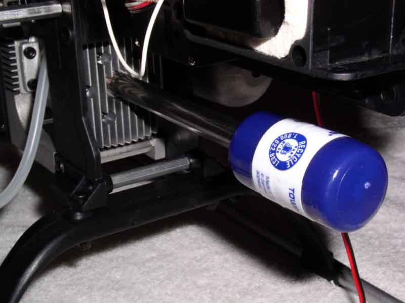
The fuel tubing lines have been connected to eliminate fuel spillage. Disconnect the line from the muffler side of the fuel tank going through the helicopter frame. The fuel filter will stay with the line going to the fuel tank. The line on the left side of the tank (muffler side) connects to the nipple on the muffler to provide a slight pressure to the tank during operation. The two fuel lines on the right side of the helicopter connect with the fuel filter in the middle between the carburetor and the fuel tank pickup line.
The tail boom has been disassembled to facilitate shipping. Rotate horizontal stabilizer mounting clamp at mid-span on the tail boom. Carefully rotate it approximately 90 degrees and at the same time delicately re-positioning the tail rotor pushrod into the groove.
Remove the two screws in the mounting block and attach the horizontal stabilizer (the white plastic 'fin' approximately 8" in span). Tighten both screws snugly.
Review the instruction manual on the page instructing how to assemble the tail-boom. Loosen the four screws on the tail boom clamp, remove both screws on the left and right side of the helicopter just below the clamp where the boom supports are mounted. Be sure the drive belt is not twisted. Give it a 90 degree rotation according to the drawings in the Kyosho instruction manual. Insert the boom and carefully place the belt over the drive gear. Once inserted a certain distance, the boom will not rotate because it is keyed for alignment.
Tension the drive belt slightly and tighten the four clamping bolts while holding tension on the boom (APPLY A DROP OF LOCTITE TO THE NUTS PRIOR TO TIGHTENING). Assemble the boom supports to the side of the helicopter main frames with one screw on each side of the helicopter (LOCTITE HERE TOO). Orient the horizontal stabilizer to parallel with the ground and tighten the clamping bolt. After assembly, rotate the main rotor and listen for abnormal noises. A slight belt whine is typical.
Assemble the tail rotor blades. Note their direction before assembly. The blade bolts must be 'loosely' tightened. It should take approximately a 1/2 or 1 pound force at the tip of the blade to make it swivel in the grip. Try to make both blade bolts equally tight.
Clip the tail-rotor servo lead into the fuselage frame at two locations. The servo wires are delicate and will fit tightly, use a tiny tool to pry the tab outward if necessary. Connect the tail rotor servo lead to the gyro.
Assemble the main rotor blades to the rotor grips. From a top view, the rotor system will rotate clockwise. The metal washers are placed on between the top surface of the rotor blade and the blade grip. Tighten the bolts gently so that the blades are free to swing fore and aft. A good rule of thumb is to tip the helicopter on it's side and position the blade grip horizontal to the ground, the weight of the blade should be almost, but not quite, enough to make it swing with gravity. Be very careful to keep the blades aligned with the rotor grips, do not allow the blades to swing without supporting their weight, they will create large loads in the linkages that control the twisting of the blade grips.
==================================
Making things move!
Make sure the circular connector on the radio transmitter is connected to 'itself'. We are doing this without aid of the Heli-Chair console at the moment. Power on the transmitter. Verify that all toggle switches are up. If the display does not read "BOX1" then change model modes as follows: Press and hold the upper left button on the computer screen sub-panel. After rotating the large dial to the "model" menu, press it once. Now rotate the large knob through the model memories to BOX1 and then press and hold the large dial. It will ask you for confirmation, press the dial again to confirm. Now hit the exit/end button until you are out of the program mode. You will see "BOX1" displayed on the screen. Now you can power on the helicopter.
Move the right control stick (cyclic) on the transmitter and watch the swashplate on the helicopter move. The plate should tilt in exactly the same direction as you have moved the stick. Moving the left stick up and down (the collective) will cause the swash plate to move up and down. Note the index marks molded into the plastic support at the aft side of the swashplate. The metal pin should approximately be at the bottom mark with the stick down and just above the top mark with the stick up. The intermediate index mark is the approximate hover point. Move the left stick to the left and right to see the tail rotor move. Visualize the pitch of the tail rotor blades like a ceiling fan. Remember the main rotor spins clockwise viewed from the top down. Verify that a right stick input causes the tail rotor to blow air the the right side of the helicopter, thus causing the helicopter to yaw to the right!
===========================
Rotopod Training Gear
The Rotopod includes assembly instructions and diagrams that may be helpful. There are images of the rotopod in the training video that will help you as well. There is a small wooden dowel rod included with the Rotopod that has a specific purpose. Insert the dowel in the hole in the bottom surface of the white nylon block. The purpose of this component is to prevent the Rotopod from squishing all the way flat after a hard landing, which would overstress the nylon block.
Remove the small screws from the end of each of the carbon legs and place a whiffle ball onto the leg, secure it with the screw and avoid over-tightening. Rotopod has recommended epoxying the blue threaded inserts into the legs and I have found that they do not tend to stay in there very well.
Insert each of the 5 carbon legs into the nylon block. The legs go into the angled set of holes (there are a total of 10 holes around the perimeter of the block. The second set of flat holes can be used for a less-safe but more instructive training setup. NOTE: it may be difficult or seemingly impossible to seat the leg all the way into the hole but this is critical. During flight testing I have had a leg wiggle loose because I did not tighten it properly. This can be catastrophic. Rotopod recommends using screws to anchor the legs into the block. If you successfully press them ALL the way into the hole, you will find this un-necessary. If you do use the screws, do not over-tighten them.
The training gear is now ready for use. The through bolt clamping the assembly together can be tightened to restrict motion, however this masks control inputs when learning to fly. The bolt should be loose enough to allow the helicopter to spin and tilt rather easily. The wooden dowel rods cliped to the aluminum cross bar are taking the place of the helicopter skids. When ready for flight, the helicopter is placed on the training gear and clipped into the spring clamps the same way as the wooden dowels. The helicopter's main mast (which the rotorblades rotate around) should be centered over the pivot bolt of the RotoPod when assembled.
================================
Heli-Chair
Assemble the collective to the chair: Connect the 6 pin plug, use two tie-wraps to secure the plug; the tie wraps should go around the connector in length, fitting between wires to secure the connector from accidental dis-connect. Tuck the wires bundle the collective riser. Gently insert the collective riser into the base. Rotate back and forth if necessary. Be very careful not to pinch the wires. For now, do not tighten the bolt completely as you will adjust the angle of the collective to your preference after assembly of the chair.
Assemble the chair to the frame using a screwdriver and wrench. Do not over-tighten the small bolts
Assemble the cyclic to the Heli-Chair. Remove the two bolts and clamp from the port (left) side of the frame. Connect the 6 pin connector and secure with tie-wraps in the same fashion as the collective. Insert the cyclic cross tube into the clamp on the starboard (right) side of the frame. Center the assembly on the frame and loosely tighten the starboard clamp. Install the port clamp (the open clamp) and loosely snug the bolts. You will now sit in the chair and adjust the collective and cyclic to your preference.
The cyclic assembly has spring centering in all directions. Left and right is factory adjusted and should remain set for the life of the product. To adjust the location of fore/aft centering, first check the clamps to see that they are 'snug' but not so tight that the assembly won't rotate. Sit in the chair and rest your right arm in your lap. Grasp the cyclic with your thumb and one or two fingers. Always fly with your fingertips! [This tip applies to flying any aircraft, model or full size] The cyclic should rest at neutral in a comfortable position. When it feels just right, tighten the clamps.
The collective assembly can be adjusted slightly in that it will rotate outboard to accomodate your preference. Typically the collective will have about a 5 degree outward rotation. Tighten the clamp when you have achieved a comfortable setting.
There are a few details to cover concerning assembly of the Heli-Chair. The umbilical cord exiting the rear of the Heli-Chair is meant to connect to your radio transmitter. When not flying with the Heli-Chair or doing benchtop adjustments, fiddling or just having fun with the helicopter, you will not have the radio connected to the chair, but instead the two connectors on the radio will connect to themselves. The umbilical cord should be tied to the leg of the Heli-Chair with a tie-wrap. This keeps it out of harms way. Be careful when maneuvering the chair not to pinch or crimp the cable.
Change the transmitter to the Chair1 model memory and turn on the helicopter. Put the left stick at the lower limit and the variable rate knob (located above the right stick) at the lower limit. Turn OFF the helicopter and transmitter, then connect the Heli-Chair to the radio transmitter. Be sure the collective is at the lower limit and the throttle is at idle (the bolt on the throttle grip will be at the top. This is now the most critical testing and setup phase assembly. Turn on the transmitter and listen for abnormal beeping, noises or anything funny. If the transmitter for any reason doesn't act normal, turn it OFF! and call Heli-Chair technical support. During shipping it is possible that the potentiometers or electronics in the chair were dammaged (this is unlikely but possible). If the transmitter appears normal you can turn on the helicopter receiver; be ready to turn it off quickly if any of the controls goes beyond their normal range. Because you previously set the helicoper's controls with the transmitter (no Heli-Chair attached), nothing should move much when first turning on the helicopter. If all seems normal, you can continue with checking out the radio. Move the cyclic, collective, throttle and torque pedals to verify they are operating normally and in the correct direction.
Assembly is now complete!